

My Garage
My Account
Cart
This part fits
2018 Toyota 4Runner
Check another vehicle- Production Date: 08/2013-08/2019
- Fitting Vehicle Options: GRN28#
Toyota 69057-35240 Cylinder & Key Set
2010-2020 Toyota 6905735240
Customer Questions & Expert Answers (2)
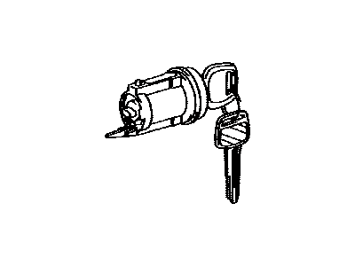
- Part DescriptionCylinder & Key Set, Ignition Switch Lock
- Part Name Code69057A
- ManufacturerToyota
This part fits
2018 Toyota 4Runner
Check another vehicle- Production Date: 08/2013-08/2019
- Fitting Vehicle Options: GRN28#
$117.69 MSRP: $167.32
You Save: $49.63 (30%)
Ships in 1-3 Business Days
1
- Related Parts
- Specifications
- Q&A
Product Specifications
Brand Genuine Toyota Part Name Code 69057A Manufacturer Part Number 69057-35240 Part Description Cylinder & Key Set, Ignition Switch Lock Other Names Cylinder & Keys, Ignition Lock Cylinder Item Dimensions 5.8 x 4.3 x 3.5 inches Item Weight 1.50 Pounds Condition New Fitment Type Direct Replacement Manufacturer Toyota SKU 69057-35240 Warranty This genuine Toyota part is covered by warranty. Shipping & Return Shipping Policy Return Policy Warning: California's Proposition 65Customer Questions & Expert Answers
- Q:Can you verify fitment for this part? Posted by ToyotaPartsDeal Specialist
- A:You can Select Your Vehicle to check if 69057-35240 fits your vehicle.Posted by ToyotaPartsDeal Specialist
- Installation and Repair Tips by AI Expert
- Removal steps 1. Park vehicle on level ground, set parking brake, remove key/fob from ignition, and note/disable any active alarm or immobilizer per owner's instructions. 2. Disconnect the negative battery terminal and isolate the cable; wait the manufacturer-recommended time for SRS/unpowered systems to de-energize (commonly a few minutes). 3. If work is near the steering column airbag or clockspring, follow airbag safety practices and avoid deploying the airbag or rotating the steering wheel while connectors are disconnected. 4. Remove or open any trim or column covers that block access to the ignition lock area-use appropriate trim tools to avoid damage and keep fasteners/clips organized. 5. Photograph or mark the relative positions of linkages, electrical connectors, and any actuator/lock orientation for reassembly reference. 6. Disconnect electrical connectors attached to the ignition lock assembly; label connectors if multiple similar plugs are present. 7. Release any retaining clips, retaining rings, or locking tabs securing the lock cylinder/assembly-note that the release method varies by design. 8. Withdraw the lock cylinder or entire ignition lock assembly gently, guiding wiring and linkages free; retain small springs or tumblers if present. Installation steps 1. Verify replacement part matches original and that you have required keys or programming credentials before installing. 2. Position the lock cylinder or ignition assembly into place, aligning it to the same orientation noted during removal; ensure linkages are routed without binding. 3. Reinstall retaining clips, rings, or fasteners to secure the assembly-use the original hardware where possible and keep components seated correctly. 4. Reconnect all electrical connectors and any mechanical linkages, confirming each connector locks in place and wiring has clearance from moving parts. 5. Refit trim and column covers, reinstalling fasteners or clips and ensuring no wires are pinched. 6. Reconnect the negative battery terminal and clear any stored codes or warnings only if you have the correct diagnostic tool and instructions; wait briefly for systems to power up. 7. Test operation: verify key or push-button functions, accessory positions, engine start/stop, steering lock/unlock, and that warning lamps behave normally; if the vehicle has an immobilizer or transponder, confirm the key is recognized or perform required programming. 8. If any binding, electrical faults, airbag warnings, or immobilizer issues occur, stop and consult a professional with the appropriate diagnostic tools. Repair tip: Keep small springs, tumblers, and clips in labeled containers during the job and take reference photos before disassembly to simplify correct reassembly.
- Q:
Why choose Toyota Parts Deal
- Dedicated Service
Your complete satisfaction is our #1 goal
- Lowest Prices
Best deals on genuine OE parts from dealerships
- Fast Delivery
Orders are processed and delivered promptly