My Garage
My Account
Cart
This part fits
2008 Toyota Avalon
Check another vehicle- Production Date: 07/2007-03/2010
- Fitting Vehicle Options: GSX30
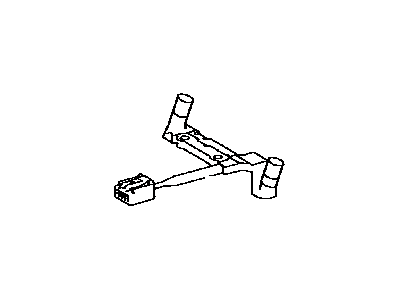
Toyota 89413-33030 Transmission Revolution Sensor
2007-2018 Toyota 8941333030
Customer Questions & Expert Answers (4)
- Part DescriptionSensor, Transmission Revolution
- (J)
- Part Name Code89413B
- Replaced By
- ManufacturerToyota
This part fits
2008 Toyota Avalon
Check another vehicle- Production Date: 07/2007-03/2010
- Fitting Vehicle Options: GSX30
$251.48 MSRP: $360.60
You Save: $109.12 (31%)
Ships in 1-2 Business Days
1
- Related Parts
- Specifications
- Q&A
Product Specifications
Brand Genuine Toyota Part Name Code 89413B Manufacturer Part Number 89413-33030 Part Description Sensor, Transmission Revolution Item Dimensions 9.7 x 10.0 x 9.6 inches Item Weight 0.50 Pounds Condition New Fitment Type Direct Replacement Manufacturer Toyota SKU 89413-33030 Warranty This genuine Toyota part is covered by warranty. Shipping & Return Shipping Policy Return Policy Warning: California's Proposition 65Customer Questions & Expert Answers
- Q:I just want to confirm I'm purchasing a correct part before placing an order Posted by ToyotaPartsDeal Specialist
- A:You can Select Your Vehicle to check if 89413-33030 fits your vehicle.Posted by ToyotaPartsDeal Specialist
Installation and Repair Tips- Q:What are the Speed Sensor(s) and their locations in the U250E 5-speed transaxle and the U660E/U760E 6-speed transaxles on 2007 through 2015 Toyota Avalon? Posted by Customer
- A:The sensor(s) in the U250E 5-speed transaxle (2009 and earlier four-cylinder models) consists of two speed sensors - one for the turbine (input) shaft located on the front of the transaxle, and one for the counter gear (output) shaft located on the top of the transaxle. To replace these sensors, the electrical connector is disconnected, the sensor is unscrewed from the transaxle, and the O-ring is replaced. On the other hand, the U660E/U760E 6-speed transaxles (all other models) only have one speed sensor, which is mounted inside the transaxle on the top of the valve body. Replacing this sensor requires removing the transaxle fluid pan, filter, and valve body, which is best done by a transmission specialist due to the sensitivity of the valve body.Posted by ToyotaPartsDeal Specialist
- Additional Installation and Repair Tips by AI Expert
- Removal steps 1. Park on level ground, set the parking brake, chock wheels, and wear eye protection and gloves. 2. If required by design to access the sensor, raise the vehicle and support it securely on jack stands. 3. Disconnect the negative battery terminal and isolate it to prevent electrical shorts. 4. Locate the speed sensor (typically on the transmission housing or wheel hub in most vehicles) and expose the connector and mounting area. 5. Depress the electrical connector tab and carefully unplug the sensor; inspect the connector for corrosion or damage. 6. Remove the sensor's retaining fastener(s) or retaining clip(s) as required by the design; keep any reusable hardware separate. 7. Gently withdraw the sensor from its bore or mounting location; twist slightly if it is stuck and avoid prying on the wiring. 8. Inspect the mating surface, bore, wiring, and any O-ring or seal; clean the area and set contaminated parts aside for replacement if damaged. 9. Protect the opening (use a clean rag or plug) to prevent debris from entering while the sensor is removed. Installation steps 1. Confirm the replacement sensor matches the original and that any new O-ring or seal is included and correct. 2. Lightly lubricate the O-ring or seal with an appropriate lubricant if the design calls for it (follow part guidance). 3. Carefully seat the new sensor into the bore without forcing it and ensure it is fully and evenly seated. 4. Reinstall the retaining fastener(s) or clip(s) and snug them securely by hand and with tools-use manufacturer-specified tightening method or torque if available. 5. Reconnect the electrical connector until the locking feature engages and verify the wiring is routed without sharp bends or contact with moving parts. 6. If a wheel or other components were removed, reinstall them and secure per manufacturer procedures. 7. Lower the vehicle if raised and remove wheel chocks and jack stands. 8. Reconnect the negative battery terminal and tighten securely. 9. Start the vehicle, observe instrument cluster lights (ABS/speedometer), clear and scan for any diagnostic trouble codes, then perform a short road test to confirm correct speedometer/ABS operation and re-scan afterward. 10. Repair tip: label connectors and routing before disassembly, and replace any damaged O-rings or corroded connectors to prevent future faults.
- Q:Where is the speed sensor that s located on the transmission in the 14 2.5 Camry? Posted by Customer: 2014 Toyota Camry
- A:89413-06010Posted by ToyotaPartsDeal Specialist 18/6/2025
- Q:
Why choose Toyota Parts Deal
- Dedicated Service
Your complete satisfaction is our #1 goal
- Lowest Prices
Best deals on genuine OE parts from dealerships
- Fast Delivery
Orders are processed and delivered promptly