
My Garage
My Account
Cart
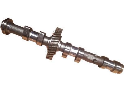
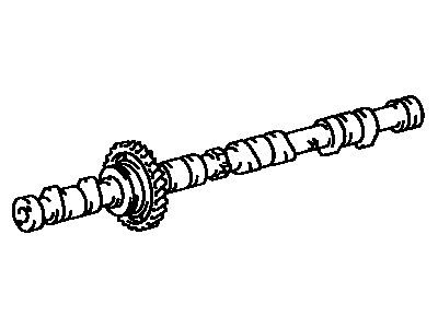
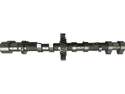
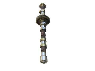
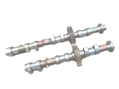
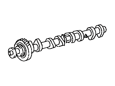
Genuine Toyota Tacoma Camshaft
Cam- Select Vehicle by Model
- Select Vehicle by VIN
Select Vehicle by Model
orMake
Model
Year
Select Vehicle by VIN
For the most accurate results, select vehicle by your VIN (Vehicle Identification Number).
25 Camshafts found
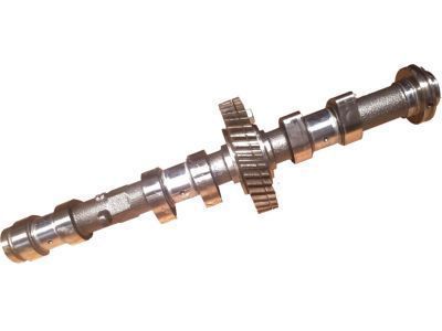
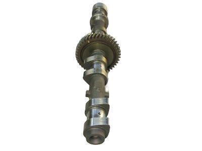
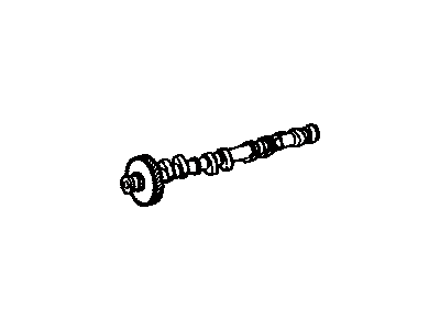
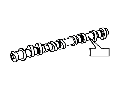
Toyota Tacoma Camshaft Sub-Assembly
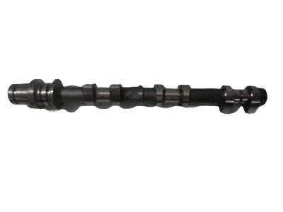
Part Number: 13054-62030$231.76 MSRP: $332.32You Save: $100.56 (31%)Ships in 1-3 Business DaysToyota Tacoma Camshaft
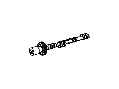
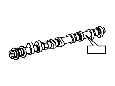
Part Number: 13501-31040$537.83 MSRP: $803.06You Save: $265.23 (34%)Ships in 1-3 Business DaysToyota Tacoma Camshaft
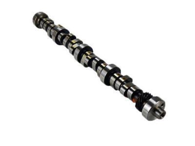
Part Number: 13502-62030$231.76 MSRP: $332.32You Save: $100.56 (31%)Ships in 1-3 Business DaysToyota Tacoma Camshaft Sub-Assembly
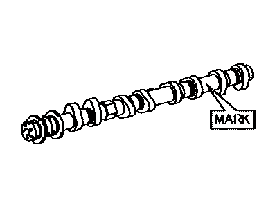
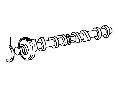
Part Number: 13053-62050$336.97 MSRP: $483.19You Save: $146.22 (31%)Ships in 1-3 Business DaysToyota Tacoma Camshaft
Part Number: 13502-31010$537.83 MSRP: $803.06You Save: $265.23 (34%)Ships in 1-3 Business DaysToyota Tacoma Camshaft Sub-Assembly
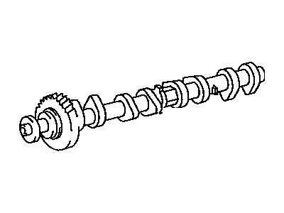
Part Number: 13054-31010$537.83 MSRP: $803.06You Save: $265.23 (34%)Ships in 1-3 Business DaysToyota Tacoma Camshaft Sub-Assembly
Part Number: 13053-31010$537.83 MSRP: $803.06You Save: $265.23 (34%)Ships in 1-3 Business DaysToyota Tacoma Camshaft
Part Number: 13501-75070$317.60 MSRP: $455.41You Save: $137.81 (31%)Ships in 1-3 Business DaysToyota Tacoma Camshaft
Part Number: 13501-75030$426.48 MSRP: $636.22You Save: $209.74 (33%)Ships in 1-3 Business DaysToyota Tacoma N Camshaft Sub-Assembly
Part Number: 13501-75071$317.60 MSRP: $455.41You Save: $137.81 (31%)Ships in 1-3 Business DaysToyota Tacoma Camshaft
Part Number: 13502-75050$311.80 MSRP: $447.09You Save: $135.29 (31%)Ships in 1-3 Business DaysToyota Tacoma N Camshaft Sub-Assembly
Part Number: 13501-0P030$427.81 MSRP: $638.21You Save: $210.40 (33%)Ships in 1-3 Business DaysToyota Tacoma N Camshaft Sub-Assembly
Part Number: 13502-75080$397.93 MSRP: $593.64You Save: $195.71 (33%)Ships in 1-3 Business DaysToyota Tacoma Camshaft
Part Number: 13501-75060$317.60 MSRP: $455.41You Save: $137.81 (31%)Ships in 1-3 Business DaysToyota Tacoma N Camshaft Sub-Assembly
Part Number: 13502-75070$397.93 MSRP: $593.64You Save: $195.71 (33%)Ships in 1-3 Business DaysToyota Tacoma N Camshaft Sub-Assembly
Part Number: 13502-0P030$427.81 MSRP: $638.21You Save: $210.40 (33%)Ships in 1-3 Business DaysToyota Tacoma Camshaft
Part Number: 13501-75040$342.74 MSRP: $511.30You Save: $168.56 (33%)Ships in 1-3 Business Days
| Page 1 of 2 |Next >
1-20 of 25 Results
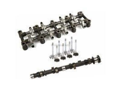
Toyota Tacoma Camshaft
If you are in demand for superior quality and affordable OEM Toyota Tacoma Camshaft, then shop with us! We own a wide range of the reduced-priced genuine Toyota Tacoma Camshaft. You can purchase in confidence as all parts come with a manufacturer's warranty. Any issues with our products? No need to worry as we have a hassle-free return policy to guide you every step of the way.
Toyota Tacoma Camshaft Parts Questions & Experts Answers
- Q: What are the steps involved in the removal and installation of the camshaft in Four cylinder engine on 1995 through 2004 Toyota Tacoma?A:When carrying out this procedure, use two service bolts, which are usually 6 x 1.0 mm bolts but 16 to 20 mm long . First, begin disconnecting the valve cover and setting the engine at TDC position for the number one cylinder, then aligning the marks found on the camshaft drive and the driven gears to the cylinder head or the valve cover mating surface. Check the camshaft thrust clearance by using the dial indicator measure; if the reading is above the service limit remove the camshaft or cylinder head. Take off the distributor if available for use then follow by the pulling of the timing chain tensioner or idler then apply a streak of paint at the area just holding the timed chain link on the timing mark of the cam sprocket. Loosen and remove the camshaft sprocket bolt and distributor drive gear while holding the intake camshaft with a wrench, and take out the camshaft sprocket and chain away. For the exhaust camshaft, compress the spring loaded sub gear with a service bolt, hold the exhaust camshaft in wrench to remove the bolt and distributor gear, and apply equal amount of loosening on the number 1 bearing cap bolt. The same procedure needs to be performed for the intake camshaft, labeling and storing of the lifters and shims for later use. Place the exhaust camshaft in a vise, with a crow's foot wrench loosen the tension on the sub-gear apply the following steps below; remove the snap ring, wave washer, sub gear and finally the camshaft gear spring. Remove the cam shaft gear and measure the free length of the gear spring.Then check all the the lifters for wear, Look at the cam lobes and the bearing journals for signs of wear or damage. Check also the oil clearance on the shaft and the journals with the help of Plastigage and measure the diameter of them and the width of the crushed Plastigage should also be measured too. Return the caps into place and check the end-play of the camshaft gears by turning them around. For installation, use camshaft installation lube on the lifters and the camshaft lobes; place the intake camshaft with the pin in the upwards direction and put the bearing caps in their appropriate positions. Loosen the intake bearing cap bolts, and after that participate in the installation of the snap ring and exhaust camshaft sub-gear accordingly as prescribed. Match the position of the camshaft gears by managing the dots and place the exhaust camshaft in its appropriate position, place the bearing caps. Torque the exhaust bearing cap bolts to 6.4 Lft.lbs, remove the camshaft service bolt and rotate to check for smoothness. Time the camshafts perpendicular to TDC, then fit the camshaft sprocket, the camshaft chain and finally the securing bolt. If fitted, fit the distributor gear and lock the securing bolt in place. Lastly, push down the plunger of the chain tensioner and turn it clockwise to install it On installating the chain make sure the engine is set to TDC for number one cylinder and check the valve clearance and ignition timing if at all required.
Related Toyota Tacoma Parts
Browse by Year
2025 Camshaft 2024 Camshaft 2023 Camshaft 2022 Camshaft 2021 Camshaft 2020 Camshaft 2019 Camshaft 2018 Camshaft 2017 Camshaft 2016 Camshaft 2015 Camshaft 2014 Camshaft 2013 Camshaft 2012 Camshaft 2011 Camshaft 2010 Camshaft 2009 Camshaft 2008 Camshaft 2007 Camshaft 2006 Camshaft 2005 Camshaft 2004 Camshaft 2003 Camshaft 2002 Camshaft 2001 Camshaft 2000 Camshaft 1999 Camshaft 1998 Camshaft 1997 Camshaft 1996 Camshaft 1995 Camshaft
