
My Garage
My Account
Cart
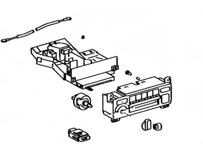
Genuine Toyota MR2 Blower Control Switches
HVAC Control Switch- Select Vehicle by Model
- Select Vehicle by VIN
Select Vehicle by Model
orMake
Model
Year
Select Vehicle by VIN
For the most accurate results, select vehicle by your VIN (Vehicle Identification Number).
13 Blower Control Switches found
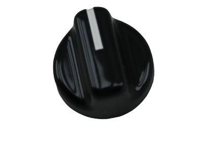
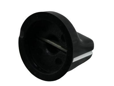
Toyota MR2 Heater Blower Switch Knob
Part Number: 84731-12010$9.98 MSRP: $13.96You Save: $3.98 (29%)
Toyota MR2 Blower Control Switches
If you are in demand for superior quality and affordable OEM Toyota MR2 Blower Control Switches, then shop with us! We own a wide range of the reduced-priced genuine Toyota MR2 Blower Control Switches. You can purchase in confidence as all parts come with a manufacturer's warranty. Any issues with our products? No need to worry as we have a hassle-free return policy to guide you every step of the way.
Toyota MR2 Blower Control Switches Parts Questions & Experts Answers
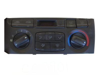
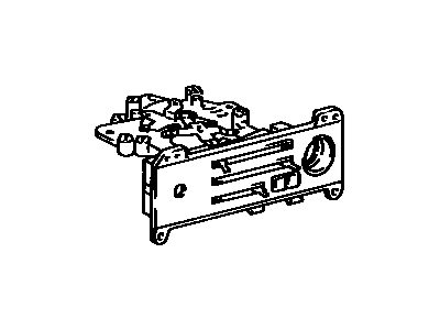
- Q: How to Locate and Check Blower Control Switches, Heater Relay, and Blower Resistor on a Toyota MR2?A:The heater blower switch is situated behind the left end of the heater control panel on the dashboard. To access it, the instrument cluster finish center panel must be removed, followed by the four mounting screws of the heater/air conditioner control panel. Once the panel is pulled out enough to disconnect the electrical connector from the back of the heater blower switch, the large locknut can be removed after taking off the knob, allowing for the removal of the switch itself. Continuity of the heater blower switch should be checked, and if it does not meet specifications, the switch needs to be replaced, with installation following the reverse order of removal. The heater relay is found under the right part of the dashboard, requiring the removal of the instrument panel under cover and the right kick panel to access it. Continuity between terminals 1 and 3 and between terminals 2 and 5 should be verified, while there should be no continuity between terminals 4 and 5; if these conditions are not met, the relay must be replaced. To test the relay operation, battery voltage should be applied across terminals 1 and 3, and continuity should be checked between terminals 4 and 5, ensuring no continuity between terminals 2 and 4; if the relay fails to operate as specified, it should be replaced. The heater blower resistor is located next to the heater relay, and continuity should be verified between terminals 1 and 2 and between terminals 1 and 3, with no continuity between terminals 1 and 4; if these conditions are not met, the heater blower resistor must be replaced.
Related Toyota MR2 Parts
Browse by Year
1995 Blower Control Switches 1994 Blower Control Switches 1993 Blower Control Switches 1992 Blower Control Switches 1991 Blower Control Switches 1990 Blower Control Switches 1989 Blower Control Switches 1988 Blower Control Switches 1987 Blower Control Switches 1986 Blower Control Switches 1985 Blower Control Switches
