
My Garage
My Account
Cart
Genuine Toyota 4Runner Piston
Engine Pistons- Select Vehicle by Model
- Select Vehicle by VIN
Select Vehicle by Model
orMake
Model
Year
Select Vehicle by VIN
For the most accurate results, select vehicle by your VIN (Vehicle Identification Number).
91 Pistons found
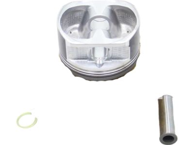
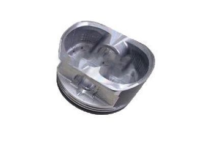
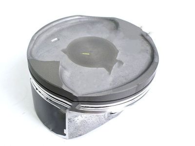
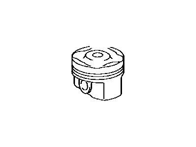
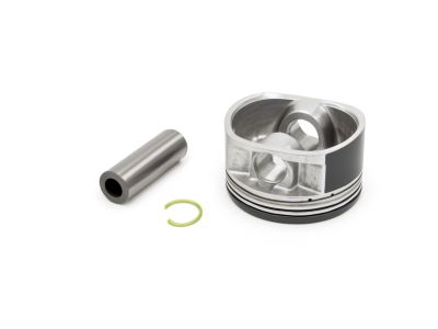
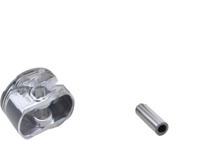
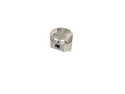
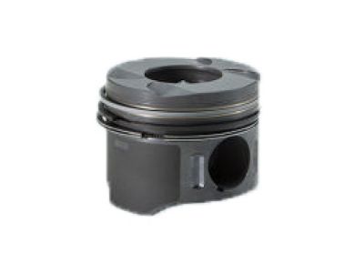
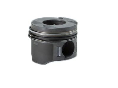
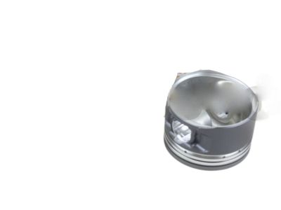
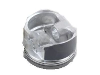
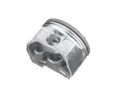
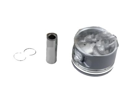
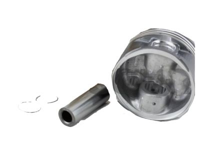
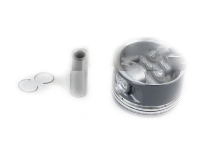
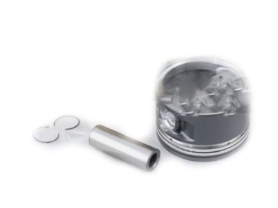
Toyota 4Runner Piston Sub-Assembly with Pin
Part Number: 13101-31030-B0$96.51 MSRP: $136.05You Save: $39.54 (30%)Ships in 1-3 Business DaysToyota 4Runner Piston Sub-Assembly with Pin
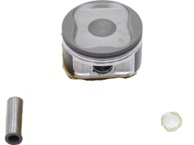
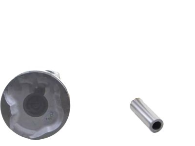
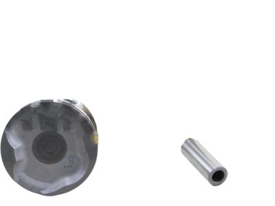
Part Number: 13101-31030-A0$96.51 MSRP: $136.05You Save: $39.54 (30%)Ships in 1-2 Business DaysToyota 4Runner Piston Sub-Assembly with Pin
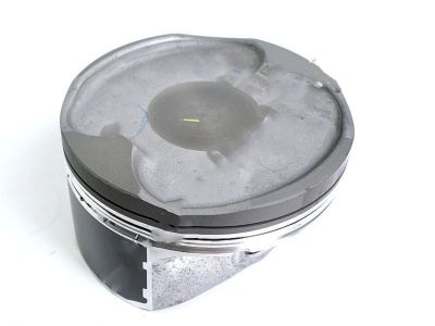
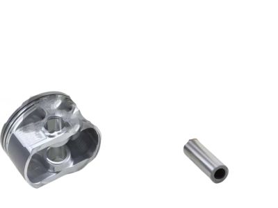
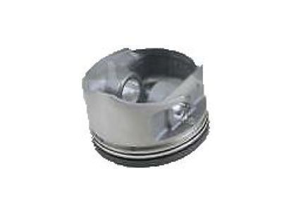
Part Number: 13101-31120-B0$93.68 MSRP: $132.06You Save: $38.38 (30%)Ships in 1-3 Business DaysToyota 4Runner Piston Sub-Assembly with Pin
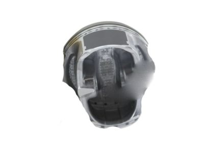
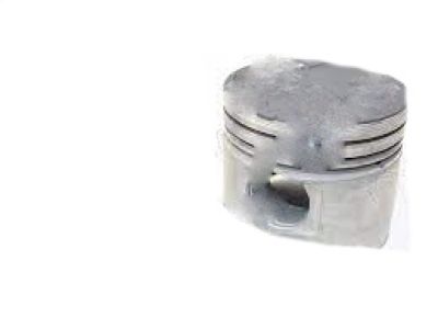
Part Number: 13101-31030$96.51 MSRP: $136.05You Save: $39.54 (30%)Ships in 1-3 Business DaysToyota 4Runner Piston Sub-Assembly with Pin
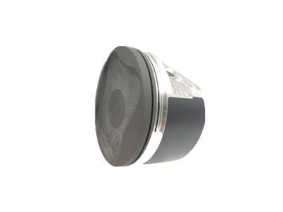
Part Number: 13101-75130$96.51 MSRP: $136.05You Save: $39.54 (30%)Ships in 1-3 Business DaysToyota 4Runner Piston Sub-Assembly with Pin
Part Number: 13103-62060$136.20 MSRP: $193.63You Save: $57.43 (30%)Ships in 1-3 Business DaysToyota 4Runner Piston Sub-Assembly with Pin
Part Number: 13101-62060-03$123.19 MSRP: $175.14You Save: $51.95 (30%)Ships in 1-3 Business DaysToyota 4Runner Piston Sub-Assembly with Pin
Part Number: 13101-62060-02$120.15 MSRP: $170.81You Save: $50.66 (30%)Ships in 1-3 Business DaysToyota 4Runner Piston Sub-Assembly with Pin
Part Number: 13101-75041$137.58 MSRP: $195.60You Save: $58.02 (30%)Ships in 1-3 Business DaysToyota 4Runner Piston Sub-Assembly with Pin
Part Number: 13101-50061-01$113.88 MSRP: $160.52You Save: $46.64 (30%)Ships in 1-3 Business DaysToyota 4Runner Piston Sub-Assembly with Pin
Part Number: 13103-75041$150.88 MSRP: $214.50You Save: $63.62 (30%)Ships in 1-3 Business DaysToyota 4Runner Piston Sub-Assembly with Pin
Part Number: 13101-31120-A0$95.80 MSRP: $135.05You Save: $39.25 (30%)Ships in 1-3 Business DaysToyota 4Runner Piston Sub-Assembly with Pin
Part Number: 13103-35042$99.34 MSRP: $140.04You Save: $40.70 (30%)Ships in 1-3 Business DaysToyota 4Runner Piston Sub-Assembly with Pin
Part Number: 13101-31030-C0$96.39 MSRP: $135.89You Save: $39.50 (30%)Ships in 1-3 Business DaysToyota 4Runner Piston Sub-Assembly with Pin
Part Number: 13103-75130$117.69 MSRP: $167.31You Save: $49.62 (30%)Ships in 1-3 Business DaysToyota 4Runner Piston Sub-Assembly with Pin
Part Number: 13101-62060-01$132.78 MSRP: $188.78You Save: $56.00 (30%)Ships in 1-3 Business DaysToyota 4Runner Piston Sub-Assembly with Pin
Part Number: 13105-35030$18.94 MSRP: $107.81You Save: $88.87 (83%)Ships in 1-2 Business DaysToyota 4Runner Piston Sub-Assembly with Pin
Part Number: 13101-35031$88.49 MSRP: $124.73You Save: $36.24 (30%)Ships in 1-3 Business DaysToyota 4Runner Piston Sub-Assembly with Pin
Part Number: 13101-35032-02$88.49 MSRP: $124.73You Save: $36.24 (30%)Ships in 1-3 Business DaysToyota 4Runner Piston Sub-Assembly with Pin
Part Number: 13101-35032-01$88.61 MSRP: $124.90You Save: $36.29 (30%)Ships in 1-3 Business Days
| Page 1 of 5 |Next >
1-20 of 91 Results
Toyota 4Runner Piston
If you are in demand for superior quality and affordable OEM Toyota 4Runner Piston, then shop with us! We own a wide range of the reduced-priced genuine Toyota 4Runner Piston. You can purchase in confidence as all parts come with a manufacturer's warranty. Any issues with our products? No need to worry as we have a hassle-free return policy to guide you every step of the way.
Toyota 4Runner Piston Parts Questions & Experts Answers
- Q: How to remove piston/connecting rod assemblies on 2003 through 2009 Toyota 4Runner?A:Before the piston and connecting rod assemblies are to be detached, the cylinder head as well as the oil pan need to be removed. Feel around the region most associated with the top of ring movement with your finger nail; the groove must be smoothed out using a specific instrument if uneven. After that, to remove the ridges, position the engine in such a way that the crankshaft is upwards. Feel the side clearance or end play using feeler gauges and should it fall outside the service limits, then the connecting rods may need to be replaced. However, you should identify mark the connecting rods and caps before loosening and removing the connecting rod cap and the bearing insert. Ex tract the connecting rod/piston assembly out through the top of the engine, if necessary using the hammer handle. It is recommended to take the measurement of diameter of connecting rod bolt and replace the one if it is below the stated size. Replace the connecting rod caps and bearing inserts back and secure the old inserts until the engine is fully assembled. With this; the pistons and connecting rods can now undergo inspections and rebuild. When reinstalling piston rings, make sure that the gap of the rings is under check; also, ensure that side clearance of piston ring is adequate. The piston/connecting rod assemblies and new ring sets should also be laid out on the bench, for easy comparison ahead. The first cylinder is to be fitted with the top ring and the end gap is to be checked with feeler gauges and altered if required. First, oil control ring should be fitted, next comes the middle and at last the top ring in correct direction. When it is time to put in the piston/connecting rod assemblies, first scrape off the rust from the cylinder walls and then angle the tops of each cylinder bore. Loosen the cap on the number one connecting rod, scrub off the bearing surfaces and bolt the new upper bearing insert in place but do not lubricate it. Align the gaps of the piston ring in 90 degrees from another, apply an oil on the piston and the rings and use the ring compressor to compress the piston rings. Place the piston/connecting rod assembly directly into the cylinder bore, the small end up, and apply oil to the cylinder walls. Insert the Plastigage at the connecting rod bearing journal and, at the end of the test, compare the width of the crushed material with that on the scale. If the clearance is not to this specification, then check the bearing inserts and the journal diameter. When the Plastigage is removed, coat both bearing surfaces with a layer of grease or assembly lube, and re-measure the connecting rod bolts, before refitting the rod cap, torque to the prescribed value. The same should be done for the other assemblies with focus on cleanliness and orientation of the photon absorbers. Once you have completed the installation of the piston and connecting rod, turn the crankshaft to test for binding while tightening the connecting rod bolt to pull the/connecting rod back to its correct endplay and recheck that of the other rod.
Related Toyota 4Runner Parts
Browse by Year
2024 Piston 2023 Piston 2022 Piston 2021 Piston 2020 Piston 2019 Piston 2018 Piston 2017 Piston 2016 Piston 2015 Piston 2014 Piston 2013 Piston 2012 Piston 2011 Piston 2010 Piston 2009 Piston 2008 Piston 2007 Piston 2006 Piston 2005 Piston 2004 Piston 2003 Piston 2002 Piston 2001 Piston 2000 Piston 1999 Piston 1998 Piston 1997 Piston 1996 Piston 1995 Piston 1994 Piston 1993 Piston 1992 Piston 1991 Piston 1990 Piston 1989 Piston 1988 Piston 1987 Piston 1986 Piston 1985 Piston 1984 Piston
